So with prototype done and tested It was time to make a proper PCB for the project. well, so I thought. The thing was that while I had designed the amplifier other people had been hard at work too. The idea was for people to be able to buy a kit containing all the needed materials for a boombox where they could plugin a their favourite player and listen to music.
The boombox project was only one of multiple kits that people could get their hands on – a DIY guitar was also available. this meant that I had to figure out a way to implement a guitar pre-amp into my system. also, since I only had one speaker and a mono amplifier, I should do a stereo->mono conversion in my design.
let me highlight the features of the project:
- 10W amplifier
- Guitar pre-amp
- stereo-to-mono summing
- make 100 kits ready for the festival!
- oh, here’s a fun one: the participants should be able to solder the board themselves.. goodbye SMD parts – Hello debugging!
I knew from the prototype that the design should be relatively low-noise since I have high frequency running around on the board.
I spend some time looking for a VERY simple and cheap guitar pre-amp and found this. At the time I was runnin out of time so I had to go with the design and hope for the best. I figured that I could put a potentiometer instead of the 1K and 2K resistors to change the amplification of the op-amp but I couldn’t test it. Also, I don’t have a guitar so I was taking a long-shot here.
The stero-to-mono summing is was based on the design found here. It made sense and again – I was out of time.
The only thing left was to figure out a way to change between ‘line’ and ‘guitar’ in a sensible way. I chose a 2-pole switch which would allow me to bypass the op-amp circuit (or put additional gain on my line signal). The stereo to mono converter would be the first thing the unit would see – in retrospect this was maybe the reason the pre-amp was not working properly.
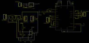
This is what I came up with
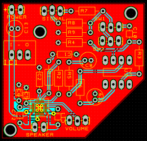
As always I’ve used DesignSpark PCB for the schematic and layout. Most of the parts I had to design myself but it works perfectly. The schematic was translated to PCB and looks like this
 I tried to make a small PCB but during the component design I forgot the with of the capacitors. The result was that some of the mouting got interesting. but it worked!
As I noted before the participants should have a hands-on experience with this project so the PCB comes with the chip aldready soldered. oh, where do I get that done? I spent some long nights with a heating gun, solder paste and a toothpick. that’s how.
So, how did it go?
We successfully made all the amplifier and boomboxes we had prepared. Okay, during my late nights of soldering, I screwed up about 10 amps but I had ordered enough extras so I could make new ones at the festival. yup, some more fine-pitch SMD soldering!
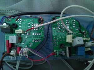
Also, You shouldn’t miss out a picture of a pair of the units. the signal is split before entering the amplifier and the summing part is left out as well as the guitar pre-amp. The system is mounted in a small backpack I use for skating trips. The power comes from a 6.8Ah LiPo power pack which sits behind the amplifiers. Sorry for the cable mess!
Here’s what you want. The design files: Rev.1
I’m working on Rev.2 and 3 which is just the amp with PTH and SMD components respectively. Stay tuned!


