

Happy new year everybody!
I know it’s been a while and wow! what a year so far! On a personal side it looks like we’re going to move sometime soon. We have put the house for sale and a looking at buying a farm instead. A farm you ask? Yes, Wouldn’t it be great to have space for a proper workshop and maybe even a pick and place machine??
Last time I wrote was to let you know that I now had 5 pens in the wild for beta-testing. So far I have only gained little more knowledge about the workings of the pen – the beta testers might not be the most active solderers (is that even a word?) in the world.
This has put me a bit back. I knew what I had to do but I kept pushing it in front of me. I needed to assemble some new boards so I could carry on the firmware development. I know I have to implement a PID regulator instead of the P-regulator I have now. that brings me to the code right away. I will give out the code for the current version when the next is ready. I know it sounds a bit harsh but IF this soldering pen is really good I don’t want it copied right from the beginning. Also that will give users some code that works but not as good as it could be.. uhm.. let me know if that is just plain stupid.
Okay, time for news. I struggled with the pen only working at 12V.
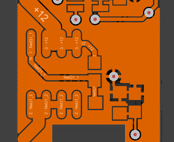 Above is a picture of the top layer where the SOIC is a huge P-FET and the single pin is the gate that connects to a pull-up resistor. It is also connected to a smaller N-FET (SOT-23 casing) that controls the bigger P-FET. the error might not be physical BUT it is there nonetheless. The N-FET was only graded for a Vds of 20V. Usually, semiconductor technology has the bad habit of failing to short. can you see what is happening then? N-Fet fails to short means that the P-FET is fully ON allowing the tip to heat without control which means a ruined tip. Those are EXPENSIVE! I was bummed out when I burned out the 4th one.
I will of course make some dummy-load next time so I don’t waste anymore tips but this means that it could still work at maybe 24V. I will definitely try this out when I get some new N-FETs.
Next I have been looking into some nice cable for the pen. The current is what I could find in my drawer. I have found some really nice looking cable but I haven’t tried it yet. It is also expensive :/
Lastly I will give away some information. Here’s the current schematic for all your nerdy needs! Drop me a line if you have comments or thoughts about this
Hope you are fine and able to setup your workshop 😉
Any further progress on project ?
Thank you for your comment 🙂 I really appreciate it!
So far I haven’t been able to do anything at all. We haven’t sold the house yet and for some strange reason the real-estate agent don’t think it will sell faster with my machines in the living room.
that means that I have put all projects on hold while we sell.
Also, I have gotten a new job – starting may 1st. This will be a lot more hands-on and hardwareoriented so I hope that I will have some time to develop on the pen.
One of the betatesters have come back and told me about a problem with the pen. he’s having some runaways so that can mean only one thing. implement the watchdog timer. a positive note will be that I can release the first working firmware since I can then produce an updated one to use myself.
Congrats on the new job! Always embrace change.
I was poking around looking for a micro soldering tip for my rework station and stumbled across your project on Hackaday. I love the idea as it is affordable for me. I build everything in-house myself including PCBs (No copper plated vias of course…). I would like to jump in for some testing.
I think you can add some feedback for your N-Fet with a few components. First, I would drop a 5v(36V Contacts) relay in front of Q2 so you could cut off the heater in an emergency should Q2 fail to short. It would leave Q1’s base floating at 12V instead of active. Second, I would swap your 10K on Q1 for a 15K and add another 10K after Q2. The point between Q2 and the 10K->GND will have a voltage drop of 7.2V giving you 4.8V output at that tap. I do this to monitor coin-op tones on another circuit I built. Feed your 4.8V tap to the Atmega an presto. As long as Q1’s base is happy with 4.8V @ .48mA it should work. Just a thought…I was thinking optocoupler but that would waste power dropping V for the LED side.
As for the runaway, I find it is usually due to a mis-programmed ISR or something is blocking. The watchdog timer will work. I’m just curious to find the bug!
Since this solder tip has a sense pin you should be able to easily implement a PID controller. One requirement is to have feedback for the PID process to self-adjust. I’m in the middle of making my remote controlled lawn mower and am in the process of programming a differential PID loop to keep 2 motors at equal speed. There is already a PID library for Arduino. Just set your 3 gains and compute. Very simple. There are some good videos out there on this.
Time to go home but I will check back. I always need a micro-iron for stupid tablets. These micro-USB’s are a PITA. I must have reflowed the last jack 6 times before all pins were set. Hit it with the iron many times, flux, iron, reflow…. eh. Happy Friday!
Any update yet? I would like to buy one.
This is so cool. Any status updates on being able to purchase one? I’d love to have one in my travel bag.
Hopefully new job is going well and house is sold.n I am still optimistic that we will see the this nice project realized one day 🙂