

One of the fundamental ideas with the soldering pen was to have a small package and a 3d printed casing for the whole project. I don’t know how it happened but somehow I completely missed the fact that the jack connector was not in the same plane as the board. of course. therefore I decided to look for a very low profile connector instead.
The first and second revision of the PCB showed that the principle was working. I could (easily) make a soldering pen with a small footprint and a nice set of features. Now I could focus more on the mechanics of the project.
I’ve found the connector: CUI SJ-3502-SMT. It’s only rated for 1A but so is most of the jack connectors I can find. My biggest problem: slotted holes!
It turns out that DesignSpark PCB can’t do slotted holes! Argh! Somehow I’ve always managed to get around this until now, but this was very much needed. What should I do? A new CAD tool is not a very funny solution.
Anyway I decided to have a look and I found CircuitMaker – the ‘free’ version of Altium, that in return requires that you store your project publicly. Fair enough I’m all for open source anyway and having a platform to share from is not that bad. At least I knew that I could get my slottet holes.
Fast forward 2 days and I’ve found out that Circuitmaker gets compoent specifications and footprints directly from octopart. this is insanely nice – crazy nice! beacuse that means that when I’m done with a component it will be shared for everybody else to use. voilá, a single global component library. wow!
Also Circuitmaker, being Altium under the hood, of course works in 3D. So almost all components have 3d models attached.
Look at this:
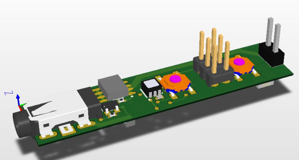
Isn’t that beautiful?The new low-profil jack connector is clearly visible and I’ve changed the LED to a SMD version.
I’m really close to removing the programming header and replacing it with…. something smaller. I have an idea for something that could fit in that space..