The nature of the project makes several controlling choices ‘the obvious choice’. The clock only needs 28 outputs for segments and 1 for the ‘dots’ in the middle of the clock (the option to turn them on and off is nice to have). finding a microcontroller with 29 outputs is not very hard, for example the PIC16F1937. Available in a 40 pin DIP package, the MCU has all the outputs including an I2C port and UART for computer control.
On the other hand I much prefer an expandable solution. Also that would give me the opportunity to write a small note on how to use the UART as a bus, instead of point-to-point communication. Using the UART this way has some serious drawbacks but the ease of operation is very compelling and I can get started right away.
To make this work I will start off by making a master-slave system with 1 master which knows the time and 4 slaves which each controls a single digit with 7 segments. The theory of operation is straight forward. Each display has a one-byte address. The master can then set the value for each digit, one at a time. This method has a number of options:
- Scalable, up to 256 digits in current configuration. Protocol could be changed to handle 16,32 or even 64 bit addresses. it is just a matter of software.
- Flexible, with multiple controllers. If one fails, the rest of the display can continue to work – might give some undesired side-effects.
- Error correction can be built-in. Using the protocol and for example CRC checking, the communication can be quite robust.
The controllers will have the following features
- will accept UART input to control the digit value
- will have 7 output with MOSFETS for high current drive (high current as in 500mA or equivalent)
- Address will be set in firmware (for now. Could be changed to EEPROM or a DIP-Switch based solution)
- Interrupt driven, for low latency during value change
- will be able to show 0-9 and blank on the output segments
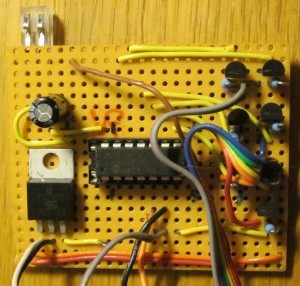
The controllers have gone through several revisions. The first was the breadboard solution showed in a previous post. The next is the one below.
 The controller MCU is the same, PIC16F688 in a DIP-package. the output stages are MOSFETS in TO-92 housing. Supply is 12V for the segments, with a 7805 linear regulator for MCU voltage. The MCU draws so little current that a voltage divider might do, but the quite substantial changes in current during digit changes requires some serious stabilization on the MCU side of the regulator. The ribbon cable on the right side is to the segments.
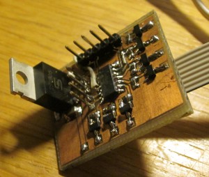
After some consideration the next revision of the controller board was made. The next version was a bit smaller and utilized the copper traces on the back of the breadboard.
 The components are still the same but the segment output has a SUB-D connector soldered directly to the breadboard. The idea was to make display changes easier. The ribbon going out at the top of the picture is the programming header, the ribbon on the low side of the picture is supply and bus connections.
It wasn’t too hard to figure out that the controller boards would have to go on ‘real’ PCBs sooner or later. If the layout would use SMD components only the layout could be contained inside the display housing. this would require that the PCB is either single-sided or has plated holes. Since I have done the PCBs at home they are neither. Therefore the idea of the controller being located inside the display housing was scrapped. Also, if something did go wrong I would have to open up the display – a thing I would rather be without.
The PCB mounted controller has been assembled and it is very clear that I can’t have programming header, regulator and supply/bus pins attached if the controller board should be inside the display housing.
 Instead I have chosen to put the controllers next to the main controller. An idea I got at the same time I moved away from the SUB-D connectors on the previous controller board. I need 7 cathodes and one anode. 8 connections in total. I accidentally stumbled across an old 4-port router which had a very nice 4-port RJ-45 connector. This means that the displays will be equipped with an RJ-45 connector and the controller box will have a 4-port connector. This also means that I can use simple (and cheap) ethernet cables for the connections to the displays. A bonus feature is the locking tap which will ensure that the cables don’t get loose by accident – smart!

