Finally got around to write the last post on the automated drawer light.
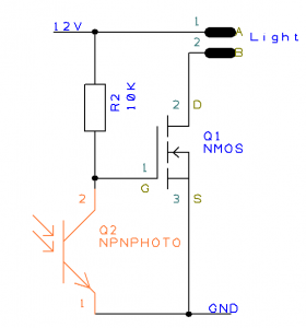
The circuit is really simple. the 12V is always on. when the IR LED is shining light on the photo transistor, it conducts. This result in the gate of the NMOS (Q1) is being pulled low. Again, this turns off the output. when the IR LED is not opening the phototransistor, the pull-up resisitor (R2) pulls up the gate of Q1 and the light is on.
The total current consumption of the circuit is a bit high – the IR LED is always on and even when the output is off, the phototransistor is also conducting current. Furthermore, the value of R2 is a bit to high, so the photo transistor can’t pull Q1 all the way down, but the light is always a tiny bit on. This increases the current consumption, but can quickly be solved by changing the R2 value to for example 4,7K
Diagram in DesignSpark format: Layout.sch


