

Disclaimer: This is also posted as my entry for teh Hackaday prize: https://hackaday.io/project/10140-soldering-pen
The soldering iron. One of the most used tools on the bench. We all have a preference for our own.
One of the problems is that a proper soldering station is quite expensive. Take the Weller XMRP for example. Amazing tips, fast heating and great for really fine-pitch work.
The tips are withing a hobbyist pricerange but the controller is expensive. Very expensive.
A few people have already built arduino based controllers for the tips. What I want is essentially that. But smaller.
This project doesn’t claim to be anything it isn’t.
It’s not a big soldering station with all the bells ans whistles.
Instead it’s a small PCB that will control a Weller RT tip and allow you to set the temperature within 10 degrees.
Also, it will allow the soldering tip to power down when you’re not using it. in fact, about the same control as any soldering station. just smaller.
The project has its roots in the SMD soldering station by Martin Kumm: http://www.martin-kumm.de/wiki/doku.php?id=Projects:SMD_Solderstation
Some years ago I got a tray full of ATMEGA168’s and since then I’ve always wonderes why people made shields for Arduinos. i mean, Just put the controller on the PCB when you’re designing anyway. And since I got a bunch of them I might as well.
I figured that I didn’t need a display for my soldering station. Why would I? I usually use the same temperature and only when soldering on large ground planes would I need some extra ‘oompf’. For tasks like that I would usually take a bigger soldering iron anyway.
Thus the minimal soldering station was born. no display but with a USB interface for computer control.
the outline of the project was almost clear:
- Support Weller RT tips
- Visual indication of heating and ‘ready to solder’
- support cooldown switch
- store temperature in EEPROM
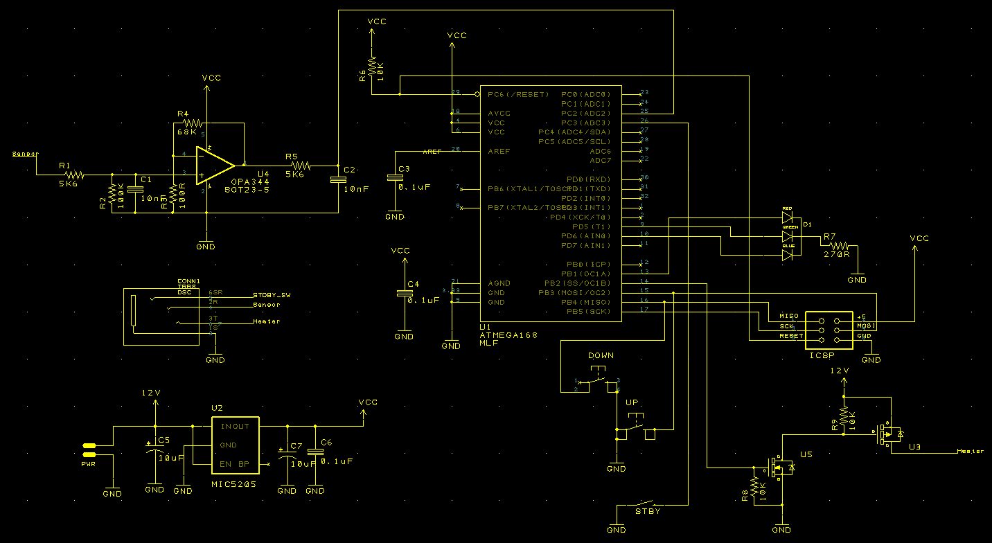
I sat down and drew a diagram.
 Now – the waiting game. I’m all too familiar with the time that goes between PCB ordering and actual delivery. feels like months!
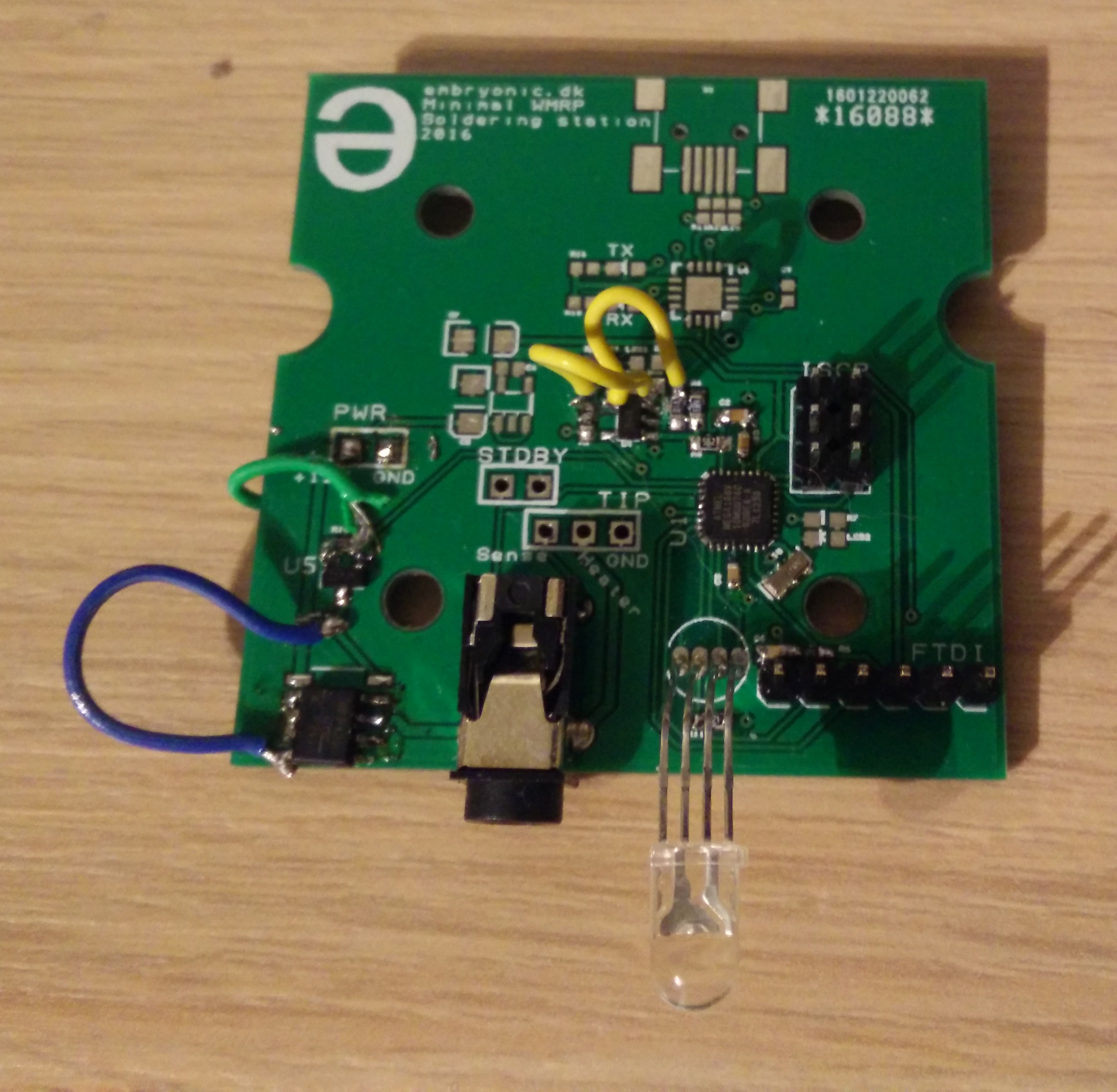
After a few weeks though, they arrived:
So which came first – the chicken or the egg?
I have a tray with ATMEGA168’s. the only problem is that the package – MLF. In other words, No leads and damn small. Lucky I have tried soldering fine-pitch no-lead packages before, but this is getting ridiculous. how will I solder my new soldering station? with the very tip that I’m building a station for. It’s like brain surgery on yourself.
Luckily I have access to a real Weller station at work so during my lunchbreak I quickly soldered a MCu to one of my PCBs. Back home I could then put on headers and ‘big’ components, like 0603 resistors and caps.
First light
It’s always interesting when a new board is powered on the first time. Will it let out the magic smoke? will it just don’t work? Even though I have done plenty of projects I’m still not sure what to expect at the first power-on. could it be THAT time when it just explodes in your face without warning?
Hesitantly I turned on the power and …. nothing. well. phew, no smoke, no explosion, not today at least.
I put on the ICSP header just to find that I have put it on mirrored. Damn. Made a new adapter and uploaded a blink sketch. yay! light! MCu is working along with Oscillator and the LED. so far so good.
Too much light
The next thing was the analog front-end. This is the part where I have been using the design from Martin Kumm. I actually tried to write him a long time ago and ask permission but he never replied. I guess that the open source still applies when his work is still online with the license text so I soldered up the Op-amp.
again, nothing. After a quick inspection I found that the opamp had the inputs switched. Damn damn.
cut traces and add wires. signal? Check!. Okay, now I could sense the temperature of the tip, reading a stable 25/26 degrees. I took my still hot soldering iron and touched the ned RT tip. the temperature was rising! fast! fantastis, that meant that the sensor was giving me readings. that would work.
next up was the power output: PMOS with an NMOS to provide the right signal type. The big moment – power on with the tip.
and BAM. disaster. In what turned out to be a reverse PMOS (I really screwed up with mirroring this time huh?) The body diode of the beefy FET was providing a clean path through the RT tip and before I could do anything the tip was glowing an eerie red. I turned the system off as fast as I could but the damage was done. the heating element of the tip was destroyed. resistance read 390ohms. Dang.
Thanks for sharing this.. I was also looking for some cost-effective alternative.. Will try this.. Hope it works with me 🙂