

I’ll start with a picture.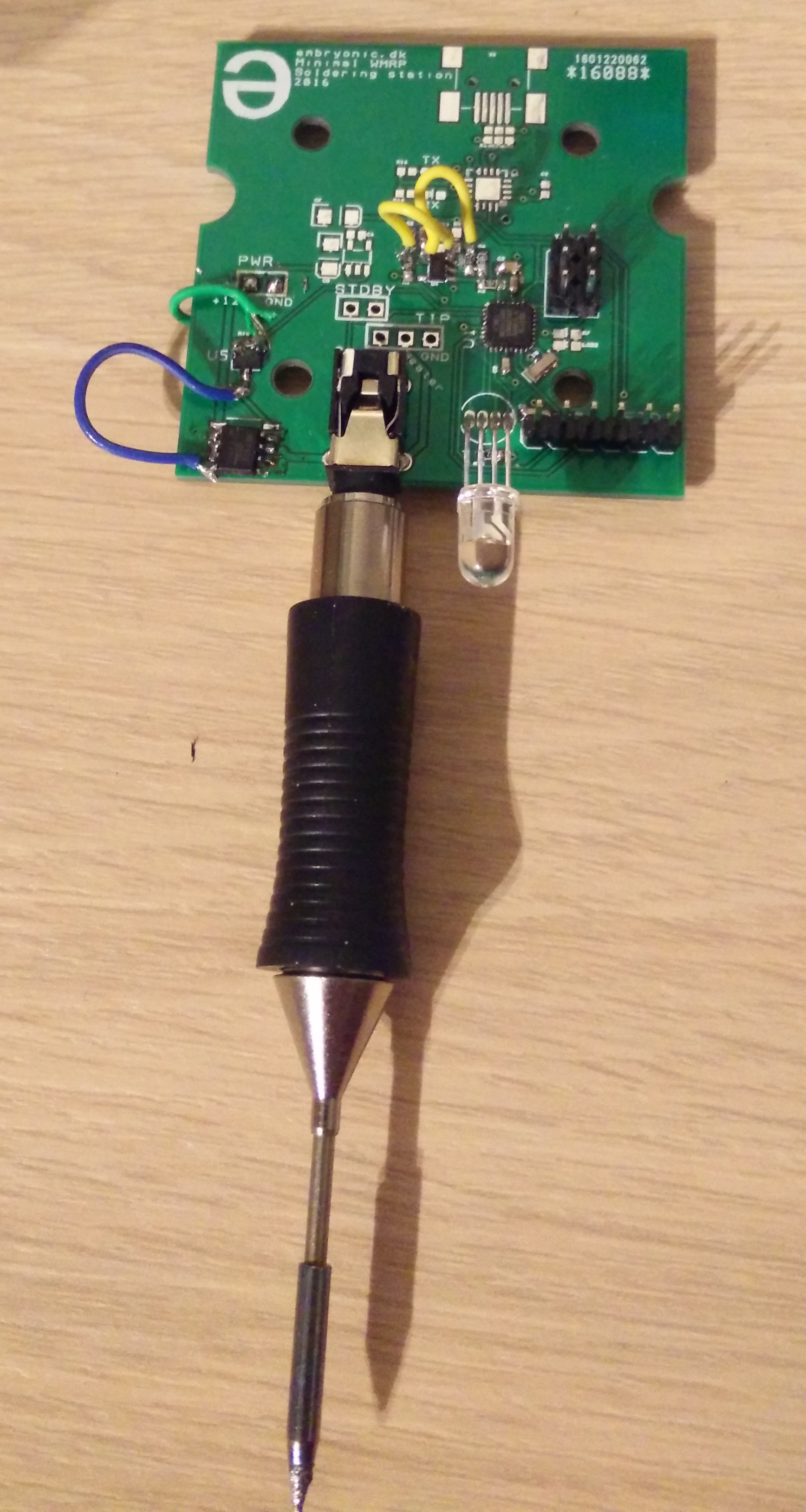
this is the mini soldering station I have started working on. What you can see is the RT tip directly attached to the controller board. the idea is of course to have a mini-jack extension cable in between, but then it hit me. why?
Why don’t I just make the whole system small enough to fit into the same width as the tip? If I let go of the USB connection and instead add a button or two all I need is a method of indicating the temperature. Back to the drawing board.
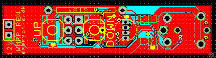
Now we’re talking!
the PCB is 12 mm wide and 50 mm long. I have been a bit creative with component sizes and placement. but it fits, even with room to spare.
Also I have solved the issue with temperature indication. The system will still store the selected temperature in EEPROM. when adjusting the red LED will blink one time for each hundred degrees (300 degrees = 3 blinks) and the Blue one time for each 10 degrees. I dont want to adjust for single degrees but other users will easily be able to adapt the firmware if they want to.
Hardware changes from the first ‘station’ version: No FTDI header – only ICSP programming. also, No resonator. I don’t need serial communications so I don’t need precise timing. away goes the crystal and caps.
I’ve added a footprint for both a reed relay and a hall-effect sensor. the reed relay was my first idea but after some input I decided to put on a hall sensor. It’s also mounted at the bottom side and centered so this will likely be a much better location than the reed switch which is located on the topside to the right.
Again, the waiting game is played. waiting for PCBs… I will get started on a 3d printed casing while I wait.